
How Should M-Bus Cabling for Heat Meters Be Done?
The M-Bus protocol is designed for a maximum of 250 addressable meters, but when building the bus the main limiting factor is the power of the converter that feeds it.
more efficient tomorrows
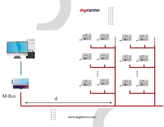
The M-Bus protocol is designed for a maximum of 250 addressable meters. There is no master address. Several addresses are reserved for collective messages (broadcasts) and service telegrams, but when building the bus the main limiting factor is the power of the converter feeding it. All manufacturers specify the maximum number of meters that can be connected to their converter; sometimes the converter’s maximum current is given instead, and the number of meters can be calculated by dividing it by the so-called unit load (1.5 mA — the typical current consumption of a meter that is not communicating). The M-Bus is powered by the converter: at rest the converter’s output voltage should be 36 V DC, and during transmission the converter lowers the voltage to 24 V to send data.
The problem arises from the resistance of the bus line. Because the meters draw current continuously, a voltage drop occurs along the line, so at more distant meters we no longer measure 36 V but a lower value. However, the voltage must not fall below 24 V at any point on the bus. During transmission, a drop of 12 V represents the minimum bus voltage of 12 V required to supply the meters successfully.
How should the M-Bus wiring diagram look, and what should you watch for when laying cable?
If M-Bus cabling is not done correctly or unsuitable cable is used, problems can occur in data transmission. Here are some important points and cable choices for M-Bus cabling:
M-Bus cabling
- Topology: an M-Bus network usually uses a “daisy-chain” topology, meaning a series of devices each connected to the next. Cables should run through the devices and connect to the next device.
- Cable length: M-Bus cabling distances must comply with the maximum lengths stated in the devices’ technical documents. As cable length increases, signal attenuation may occur and affect data transmission.
- Avoiding electrical noise: the M-Bus cable should be resistant to electrical noise, which increases the reliability of data transmission. Keep it away from electrical panels, high-voltage equipment and other noise sources.
- Cable route and protection: lay cables so that they are protected against physical damage; provide suitable protection and waterproofing at underground crossings.
- Connections and connectors: twist and insulate cable ends correctly; connect connectors tightly and correctly.
Cable selection
The following cable types are usually preferred for M-Bus cabling:
- M-Bus cable: cables designed specifically for M-Bus systems are available; they are usually shielded and made of high-quality copper wires.
- Shielded cable: commonly used in M-Bus systems, it protects against external electromagnetic interference; the inner wires are covered with a metallic braid or foil to protect the data signals.
- Copper wires: copper is preferred for its electrical conductivity and durability; quality copper wires ensure reliable data transmission.
- Protection and waterproofing: especially for outdoor applications, cables must have these properties.
These guidelines are the basic principles for M-Bus cabling. Since every situation is different, a detailed assessment of the installation environment and an appropriate choice of cable are important. Following the recommendations in the devices’ technical documents and the manufacturer’s instructions is also essential.
Meter connections: series vs. parallel
Series connection
In a series connection the meters are linked like a chain: the cable from the first meter goes to the second, the cable from the second to the third, and so on, so each meter is connected to the next in turn. Example: with 3 meters in total, each is connected to the next.
Parallel connection
In a parallel connection each meter is connected separately to the main line, i.e. each meter has its own cable to the main line and they all meet at the same point. Example: if one meter has a problem, the others can still send data.
Explained simply
Series: “Imagine train carriages coupled together: the first carriage is coupled to the second, the second to the third. The meters are connected in the same way — the cable from the first meter goes to the second, from the second to the third.”
Parallel: “Parallel connection means each meter is connected to the main line separately — like separate trains each running on its own track. Each meter is connected to the main line with its own cable, so even if one has a problem, the others keep working.”
Which is better?
- Series — advantage: less cable and a tidier installation. Disadvantage: a problem in one meter may affect the others.
- Parallel — advantage: each meter works independently; a problem in one does not affect the others. Disadvantage: more cable and a somewhat more complex connection.
In general, you can choose the connection type according to your application and preference. If it is more important to you that a fault in one meter does not affect the others, choose parallel connection; if you want less cable and a tidier installation, consider series connection.